
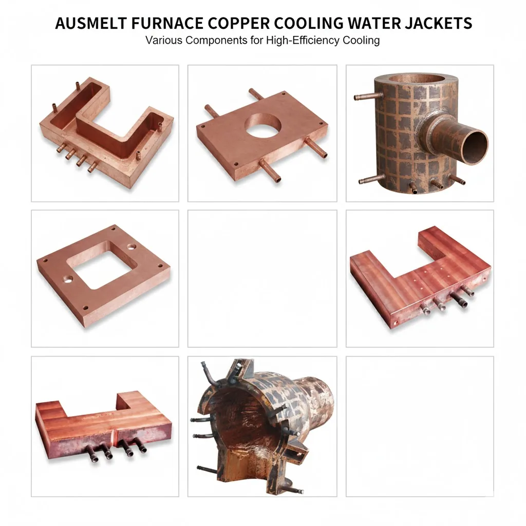
A Leak Is a Symptom, Not a Root-Cause Conclusion
A failed copper cooling plate, panel, jacket, stave, or water-cooled assembly is part of a thermal, hydraulic, mechanical, and operating system. A visible leak identifies a condition that needs control; it does not by itself prove whether the initiating cause was blocked flow, local boiling, thermal fatigue, erosion, corrosion, joining, manufacture, mounting restraint, refractory loss, impact, or an operating change.
Keep three terms separate:
- Symptom: what was observed, such as leakage, deformation, hot spot, pressure loss, reduced flow, cracking, wall loss, or joint separation.
- Mechanism: the physical process that produced damage, such as fatigue, erosion-corrosion, overheating, abrasion, overload, or crack growth.
- Root cause: the system condition or combination of conditions that allowed the mechanism to occur and remain uncontrolled.
The investigation should test credible explanations against evidence instead of assigning a cause from appearance alone.
1. Make the Equipment Safe and Preserve Evidence
- Isolate and depressurize the affected circuit under the site's approved safety procedure.
- Record the installed position, orientation, adjacent refractory or shell condition, connection arrangement, supports, deposits, impact marks, and leak location before cleaning or repair.
- Photograph the overall assembly, interfaces, damaged zone, fracture or opening, internal channel condition, welds, fittings, mounting points, and removed deposits with scale references.
- Preserve removed pieces, deposits, blockage material, water samples, seals, fasteners, and relevant maintenance parts when they may support analysis.
- Mark cut locations and orientation before sectioning. Uncontrolled grinding, cleaning, welding, or cutting can remove fracture, corrosion, surface, or deposit evidence.
Evidence preservation is part of the technical investigation. A repaired surface may restore temporary function while making the original mechanism harder to verify.
2. Build the Operating Timeline
Collect the approved drawing and revision, material and manufacturing records, installation date, repairs, circuit changes, water-treatment records, pressure, flow, inlet and outlet temperatures, alarms, trips, process upsets, start-stop history, refractory work, and adjacent equipment changes.
Compare the event with:
- commissioning and first operation;
- normal steady operation;
- starts, shutdowns, low-flow events, trips, and restarts;
- changes in process heat load, burden, bath, slag, flame, lance, or arc position;
- changes in water source, chemistry, filtration, pump, valve, hose, manifold, or circuit balance;
- maintenance, cleaning, welding, support, alignment, or refractory changes.
Trend data should be interpreted with sensor location, sampling frequency, calibration status, and missing periods visible. A normal header reading does not prove that every internal passage had adequate local flow.
3. Map the Damage Before Selecting Tests
Create a damage map that relates the observed condition to the component drawing and service orientation:
- hot-face, cold-face, edge, corner, transition, connection, weld, heat-affected zone, machined channel, plug, or mounting point;
- single location, repeated pattern, circuit-specific pattern, or system-wide pattern;
- local thinning, grooving, pitting, deposit, blockage, crack network, distortion, impact, or fracture;
- relationship to water direction, high points, low points, bends, dead zones, section changes, restraints, refractory gaps, and heat source.
Wall-thickness readings, dimensional checks, borescope records, deposit analysis, surface testing, metallography, chemistry, hardness, conductivity, fracture examination, or other tests may be selected after the evidence question is defined. PT can reveal discontinuities open to a suitable nonporous surface, but it does not find sealed internal discontinuities and does not supply acceptance criteria.
4. Test Cause Groups, Not One Favorite Explanation
Cooling-circuit conditions
Review inlet condition, available pressure, actual flow, circuit balance, passage size, bends, local losses, venting, drainage, boiling risk, deposits, scale, blockage, erosion velocity, pump or valve behavior, and connection restrictions. A pressure or leak test of the removed component proves only the defined test boundary and condition; it does not reproduce the installed thermal duty or prove field flow distribution.
Thermal and mechanical conditions
Review heat-flux distribution, starts and stops, thermal gradients, restraint, differential expansion, section transitions, local overheating, refractory support, mounting, distortion, impact, vibration, and external loads. Cracking near a transition or attachment may have more than one contributing mechanism.
Water chemistry, erosion, and corrosion
Review water source and treatment, conductivity, pH or other project-controlled chemistry, dissolved or suspended solids, oxygen, chlorides or other relevant species, velocity, galvanic contacts, deposits, crevices, and shutdown conditions. Do not infer a universal corrosion mechanism from color or deposit appearance alone; sampling location and analysis method matter.
Material, manufacturing, and joining
Verify material identity and condition, product form, casting or wrought route, channel manufacture, wall transitions, weld or braze design, filler and procedure where applicable, heat treatment, machining, cleaning, inspection stage, repair history, and traceability. An indication is not automatically the initiating defect, and a material certificate alone does not prove the finished component's hydraulic integrity or service performance.
Installation and operating change
Check alignment, supports, fasteners, hoses, manifolds, valves, gaskets, sealing faces, imposed loads, refractory contact, installation clearance, cleaning practices, process changes, and unauthorized modifications. Replacement of the component alone will not correct an external system cause.
5. Use a Verification Matrix
For each credible cause, record:
| Hypothesis | Evidence that supports it | Evidence that challenges it | Test or record needed | Owner | Status |
|---|---|---|---|---|---|
| Example: restricted passage | Deposit at mapped passage; flow history changed | No restriction found in adjacent circuit | Borescope, section, deposit analysis, circuit comparison | Project team | Open |
Keep observation, interpretation, and conclusion in separate fields. Where evidence has been destroyed or operating data are incomplete, state the uncertainty rather than converting it into certainty.
6. Control the Corrective Action
Corrective action may involve circuit cleaning or redesign, water control, instrumentation, mounting, refractory, operating procedure, component geometry, section transition, material, joining, inspection, or maintenance. Link each action to a verified or risk-ranked cause.
A replacement drawing change is not automatically an upgrade. Record the change basis, affected interfaces, hydraulic and thermal implications, inspection plan, approval, and monitoring after installation. One failed sample does not establish a universal service-life rule for every component or site.