
Define the Contact System Before Selecting the Alloy
Electrical contact material selection must balance current transfer, contact resistance, heat generation, heat removal, contact force, mechanical support, wear, motion, oxidation or contamination, joining, surface condition, softening, and maintainability.
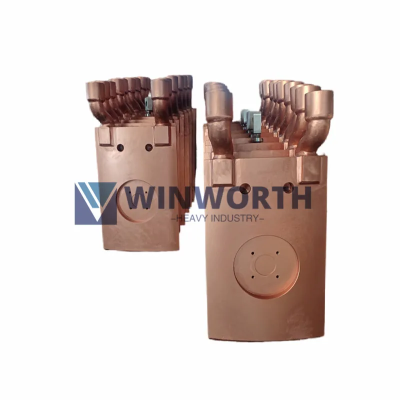
Start by identifying the actual component: SAF contact shoe, SAF pressure ring, EAF electrode clamp or holder, welding-machine contact pad, CuCrZr contact ring, rigid bus connection, water-cooled conductor, terminal, or another drawing-defined contact. Similar copper parts can carry current in different ways and cannot share one automatic material rule.
1. Electrical and Thermal Inputs
- Current type, magnitude, frequency where relevant, duty cycle, transient or fault condition, parallel path, current density basis, and allowable temperature.
- Contact-face geometry, real and nominal contact area, clamping force, pressure distribution, mating material, joint preparation, fasteners, movement, and maintenance.
- Cooling method, medium, flow, pressure, temperature, connection, monitoring, fouling, and heat-removal boundary.
- Surface oxidation, scale, dust, process contamination, arcing, fretting, sliding, repeated assembly, and expected wear.
Bulk conductivity alone does not determine joint temperature. Contact resistance, force, surface condition, geometry, connection quality, cooling, installation, and operation also matter.
2. Compare Material Directions
Commercially pure copper may support high conductivity where the approved mechanical, thermal, joining, wear, and softening requirements are compatible with the selected grade and condition.
Oxygen-free copper may be considered where controlled oxygen content, conductivity, joining, vacuum, or process compatibility is required. It is not automatically stronger or more wear resistant.
CuCrZr may be considered where conductivity must be balanced with greater strength, hardness, dimensional stability, wear resistance, or resistance to softening. Its properties depend on grade, product form, condition, and heat treatment.
Other copper alloys may be appropriate where contact force, wear, corrosion, formability, spring behavior, joining, or temperature dominates. A connector-strip alloy guide should not be applied directly to a massive furnace contact without component-specific engineering.
Copper Development Association guidance notes that temperature and alloying elements affect conductivity and that conductivity must be balanced with strength, corrosion resistance, and formability. Selection therefore cannot be made from %IACS alone.
3. Define Product Form and Manufacturing Route
- Plate, bar, forging, casting, ring, block, tube, strip, or another product form.
- Final temper/condition and any forging, rolling, extrusion, casting, heat treatment, machining, welding, brazing, assembly, coating, plating, or surface preparation.
- Material and component traceability, test location, property direction, sampling, and relationship between sample and delivered part.
- Repair, rework, local heating, plating renewal, and change-control rules.
4. Specify Interfaces and Acceptance
- Controlled drawing, revision, datums, critical dimensions, fits, contact and mounting faces, surface finish, flatness, alignment, holes, connections, and cooling passages.
- Required chemistry, conductivity, hardness, mechanical properties, coating/plating, dimensional report, NDT, pressure/leak test, or functional evidence.
- Test method, location, temperature, stage, sampling, acceptance criteria, witness point, and report format.
A material certificate or conductivity reading does not prove complete joint ampacity, temperature rise, contact resistance, cooling performance, wear life, installation quality, or system compliance.